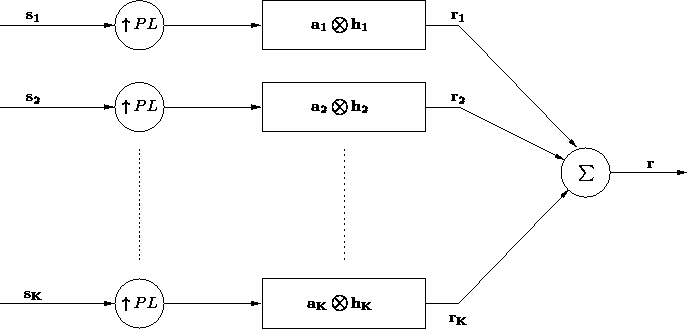
To generate realistic data with certain desired characteristics, many variables have to be chosen. Using a variation of the system model developed in chapter 2, many of these variables were easily incorporated in the generation of the received data, including user power, pulse shaping, asynchronism, delay, and spreading codes. In order to make a reasonably sized GUI, many of these parameters are chosen randomly. However, the distribution of these parameters can be manipulated through the GUI. For example, to make a realistic system, each user must have a different channel. Instead of defining each channel tap by tap, we can generate the channels randomly by specifying the distribution of the multipath. The drawback is that this limits the user's control over the individual channels. In order to make up for this limitation, there is an option for defining a specific user's power compared to all the others. For instance, you can make one user 10 dB stronger than all the others. Since the purpose of this software is to compare the general performance of linear detectors given certain system parameters, the control of individual user's parameters is limited. This design choice was made to make the GUI more usable and more readily extendable to Monte Carlo simulations. The user delay, power, noise, and spreading codes are also generated randomly. More details will follow in section 4.3.
In developing the software for generating the received data, a large
portion of time was spent computing the final data.
Generating data using the asynchronous model developed in
chapter 2 turns out to be extremely inefficient.
Since the pulse shaping filter is not a brick wall filter assumed in
the derivations, the equation for the spreading matrix is no longer,
In order to incorporate asynchronism and delay into the received data,
we changed the channel model to include these parameters. To
implement this, a square root raised cosine pulse, oversampled at 32
times the chip-rate, was created. Then a vector containing the number
of multipath rays specified, also sampled at 32 times the chip rate,
was generated. The two of these were convolved and sampled at a rate
equal to ![]() . The initial sampling position was chosen
using two parameters. The first requiring that the largest channel tap
be in the middle given
. The initial sampling position was chosen
using two parameters. The first requiring that the largest channel tap
be in the middle given ![]() , and the second adjusting for individual chip
asynchronism by adding a fraction of 32 to the initial sampling
position. Bit asynchronism was implemented by simply zero padding
the resulting
, and the second adjusting for individual chip
asynchronism by adding a fraction of 32 to the initial sampling
position. Bit asynchronism was implemented by simply zero padding
the resulting ![]() channel taps. Figure 4.4
shows the pulse shape, oversampled multipath vector, and the sampled
convolution. To see the final channel impulse response see figure
4.6. Notice there are only
channel taps. Figure 4.4
shows the pulse shape, oversampled multipath vector, and the sampled
convolution. To see the final channel impulse response see figure
4.6. Notice there are only ![]() non-zero channel taps,
and the rest are zero. These zero taps represent the bit asynchronous delay.
non-zero channel taps,
and the rest are zero. These zero taps represent the bit asynchronous delay.
To actually generate the received data vector, the structure of
![]() was exploited. It can be shown, [9] that
was exploited. It can be shown, [9] that
![]() has the form
has the form


We can generate each ![]() by convolving
by convolving ![]() with
the upsampled version of
with
the upsampled version of ![]() . This convolution is
computationally inexpensive because many of the terms in the
convolution are zero, allowing a polyphase implementation of
the impulse response defined by
. This convolution is
computationally inexpensive because many of the terms in the
convolution are zero, allowing a polyphase implementation of
the impulse response defined by ![]() . Finally,
. Finally, ![]() is
generated simply by,
is
generated simply by,