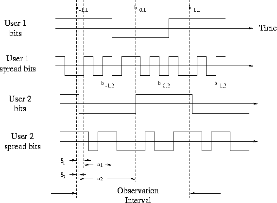
Figure 2.3: A two user system with spreading gain N=6 and observation interval 2T at n=0. The users are bit asynchronous and chip asynchronous. In this model,

The derivation of the synchronous equivalent of the chip asynchronous model
is very similar to the development of the bit asynchronous case. The main
issue now is the presence of ![]() , a non-integer chip delay. We now
define the delay from the beginning of the observation interval to the first
chip of user k, to be
, a non-integer chip delay. We now
define the delay from the beginning of the observation interval to the first
chip of user k, to be ![]() .
. ![]() can be described as
can be described as
![]() where
where ![]() is as above and
is as above and ![]() is a fraction of
is a fraction of ![]() .
.
In the bit asynchronous case, we saw that three consecutive bit
intervals contribute to ![]() . Now, we must also consider that
two adjacent chips contribute to each chip sample. Therefore, we need
to redefine the vectors
. Now, we must also consider that
two adjacent chips contribute to each chip sample. Therefore, we need
to redefine the vectors ![]() ,
, ![]() , and
, and ![]() as
as
An example of a chip asynchronous system is shown in figure 2.3.
In order to model this system in terms of our original formulation for
the bit synchronous case, we must redefine ![]() as a summation
of weighted versions of
as a summation
of weighted versions of ![]() .
.
![]()
Ideally we would like a model that also allows for arbitrary
oversampling factor and also allows for multiple antennas. The
oversampled model used in developing the simulation tools can be found
in [1, 2, 3]. It is shown in
[1, 2, 3] that the over-sampled model still can be
written in the general form of equation 2.2.
![]()
Therefore, all the receiver derivations in the following chapter can
be extended to the fractionally sampled and multiple antenna case.